1. Slope types in civil engineering
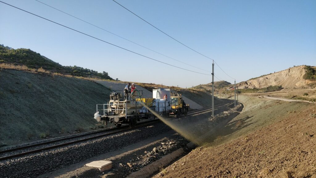
In road, rail and utility corridor construction, slopes are created either by excavation (cut slopes) or by filling (embankment slopes). The two types have different geotechnical and pedological starting points, and that has direct consequences for revegetation.
1.1 Cut slopes
Cut slopes are created by removing undisturbed soil and rock. The exposed substrate corresponds to the C horizon or the parent rock — every trace of developed soil structure is missing. Depending on the geology, carbonate-rich marl, clayey silt, sand or solid rock is exposed. The gradient is limited by the stability of the parent material, typically 1:1.5 to 1:2 in cohesive soils and steeper in rock. Erosion risk and lack of substrate are the dominant challenges.
1.2 Embankment slopes
Embankment slopes are created by placing fill material. The material placed is usually machine-compacted, has defined layers and often differs considerably in composition from the natural ground. Settlement cracks, erosion rills along layer boundaries and compaction horizons at placement boundaries are typical problem areas. Embankment slopes in German road construction are built to ZTVE-StB; that standard regulates the degree of compaction and the slope gradient — but not the requirements for revegetating the finished profile.
1.3 Slopes in special situations
Besides the classic types, civil engineering produces other slope situations with specific requirements: slopes at stormwater basins and drainage swales with periodic flooding, slopes on noise barriers with often unfavourable fill material, slopes in cuttings with seepage water emerging, and slopes under bridge structures in permanent shade. Each of these types calls for different seed mixtures, substrate preparation and choice of method.
2. Gradient as the primary planning parameter
Slope gradient is the single most important parameter for choosing a method. It determines the hydraulic loading of the surface by rainfall, the shear forces on applied material layers and the mechanical demands on the seedbed and the mulch system.
| Gradient | Ratio H:V | Suitable methods | Erosion risk | Note |
|---|---|---|---|---|
| < 18° | flatter than 1:3 | Hydroseeding, seedingby machine | low | Trafficable |
| 18° – 27° | 1:3 – 1:2 | Hydromulch,erosion control matting | medium | Profilingrecommended |
| 27° – 40° | 1:2 – 1:1.4 | HBM, geotextile+ hydroseeding | high | Profilingmandatory |
| 40° – 55° | 1:1.4 – 1:0.7 | HBM + netting,fascines | very high | Mechanicalpre-stabilization |
| > 55° | steeper than 1:0.7 | Rock revegetation,rockfall protection | extreme | Hydroseeding aloneis not enough |
Fig. 1: slope gradient and method allocation. Gradients given in degrees and as an H:V ratio. The boundaries between classes are fluid and depend on the substrate.
The slope gradient given in tender text should be stated section by section and precisely — not as a blanket figure for the whole project. Slope profiles change along a route with the terrain, the cross-fall and the ground. A tender item that simply states “slope gradient 1:1.5” frequently fails to describe the actual range of conditions on site.
3. Substrate and soil class as planning parameters
Alongside gradient, the substrate is the second decisive parameter. Same gradient, different substrate — different requirements. A sandy raw soil at 1:2 is more demanding in erosion terms than a clayey marl at 1:1.5, because sand has no cohesion and produces surface runoff as soon as it rains. Cohesive soils, on the other hand, slake in heavy rain and form crusts that inhibit germination and infiltration.
The soil class to DIN 18196 (soil groups) or DIN 18300 (earthworks) gives a first classification. For revegetation planning, the fines content (silt + clay), the carbonate content and aggregate stability are also relevant — parameters that cannot be read off from soil classes alone but that substantially influence the choice between hydromulch, HBM and a geotextile system.
4. Surface profiling: the underrated preparation step
Profiling the slope surface before revegetation is one of the most effective and most frequently neglected preparation steps. In tendering practice it is rarely listed as an item in its own right — it is usually implicit in the revegetation item, or not mentioned at all. That has consequences.
4.1 The problem with a smooth slope
Modern earthmoving machinery — long-reach excavators in particular — allows precise slope profiling from a distance. The result is geometrically exact: a smoothly graded, even slope face with minimal roughness. What counts as a mark of quality in construction terms is an unfavourable starting point for revegetation.
A smoothly graded slope has the following properties, all of which work against revegetation:
- No surface roughness: hydroseeding mixtures have nothing to key into mechanically. At gradients from about 20° the freshly applied mulch layer starts to slide in rain, before the binder has fully reacted.
- No water retention: rainfall runs off smooth surfaces in concentrated flow. Flow paths form and develop into erosion rills. Seed and fine earth are carried away.
- Tendency to slake: on fine-grained substrates (silts, fine sands) in particular, rainfall impact forms a dense surface crust that prevents germination and blocks infiltration.
- A compacted layer at the surface: grading with the bucket creates a compacted skin at the surface that hinders rooting in the first weeks.
4.2 Track marks across the fall line
The simplest and at the same time most effective way of profiling the surface is to create track marks deliberately across the fall line. After rough profiling, the slope is driven over with a tracked machine whose tracks run across the gradient — ideally in horizontal passes along the slope. The resulting track marks form a regular pattern of small transverse grooves that serve several purposes at once:
- Water retention: the transverse grooves interrupt surface runoff and hold rainfall briefly — exactly during the critical germination phase.
- Mechanical keying: hydroseeding mixtures adhere better in grooves than on a smooth face. The adhesion of the mulch layer rises measurably.
- Seed reservoir: seed collects in the hollows and is protected from drift and wash-off — a natural micro-reservoir for germination.
- Loosening the surface: the track action breaks up the surface compaction created by grading and improves contact between seed and substrate.
- Concentrated runoff
- Mulch film slides off
- Erosion rill
Result: runoff, erosion, poor mulch adhesion, patchy germination
- Water is held
- Mulch keys into the grooves
- Seed is protected
Execution: tracked machine horizontally across the slope — tracks across the fall line, not along it
Fig. 2: the effect of surface profiling on water retention, mulch adhesion and erosion behaviour. Left: a smoothly graded slope. Right: track marks across the fall line.
4.3 Surface roughness as a quality criterion
For hydraulic application, a surface roughness of 3–5 cm is a guide value proven in practice. That is easily achieved with track marks on normal substrates. On very hard or stony substrates where tracks make only a shallow impression, hand tilling or a flail mulcher pass can be an alternative. On very soft, freshly placed fill, care is needed that the machine pass does not itself create new compaction horizons — in those cases the timing of profiling has to be chosen according to the water content of the substrate.
5. Choosing the method: criteria and decision logic
Choosing a method for slope revegetation is not a free design decision — it follows from the interplay of gradient, substrate, site conditions and requirements for the target vegetation. A decision logic that works through those parameters systematically gives more reliable results than an experience-based blanket allocation.
5.1 Hydroseeding and hydromulch
Hydroseeding is sufficient at gradients under 18° with good substrate. Hydromulch is recommended from 18° and is the standard method in civil engineering up to about 35°, provided the substrate has sufficient cohesion. The fiber rate rises with the gradient: at 20°, 150–200 g/m² is defensible; at 30–35°, 250–350 g/m² with a suitable binder should be assumed.
5.2 Hydraulically bonded fiber matrices (HBM)
HBM systems are the method of choice for gradients between 35° and 55° and for low-cohesion substrates (sand, gravel, fractured rock) at lower gradients. The binder component — biopolymer or mineral — determines the cohesive properties of the cured layer. HBM applications require particularly careful substrate preparation, because contamination of the surface (dust, loose stones, oil) impairs the bond.
5.3 Geotextiles and erosion control netting: a critical assessment
Erosion control mats and nets made from coir, jute or synthetic fibers are regularly specified in slope construction as a mechanical erosion control measure. The underlying assumption — that a physical cover prevents soil loss — does not hold in that blanket form.
The fundamental problem is the mesh size. Commercially available erosion control nets have mesh openings from several millimetres up to a few centimetres. Rainfall hitting a sloping surface passes through those openings and continues to carry sediment off the soil surface unabated. The erosive forces act directly on the substrate — the net lies over it, not under it. Under sufficient hydraulic loading the net is undercut: the substrate is eroded beneath it, the net lifts and loses what limited function it had. The system fails precisely under the conditions it was meant for.
Strong HBM formulations with suitable biopolymer binders, by contrast, deliver a continuous erosion control matrix flush with the surface, laid onto the substrate without voids. Because there is no mesh structure, there are no openings through which rainfall can strike the soil unimpeded. Sediment loss is stopped at the surface itself — not covered over. They also require no installation work and adapt to changing slope geometry without cutting or fixing.
Crack-free surface, resistant to slaking
Wood fiber skeleton + biopolymer binder
High air porosity, macropores >30 µm
Bond to the soil through a guar lead binder (green)
Rooting from day 10–14 (guide value)
- Mesh openings: rainfall strikes the soil directly
- Undercutting possible under hydraulic loading
- High installation effort, limited area output
- Continuous matrix: no rainfall passes through
- Flush with the surface — no voids
- Hydraulically applied — high area output
Fig. 3: cross-section of a hydraulically bonded fiber matrix (HBM) and a system comparison with conventional erosion control netting.
5.4 When mechanical stabilization does make sense
Nets and mats have a legitimate function — but not as primary erosion control. Where they should be used is geotechnical stabilization: rockfall protection on rock faces, temporary stabilization of loose material before hydroseeding, or as an anchoring aid for HBM layers in extreme terrain above 50°. In those contexts the mesh structure is not understood as erosion control but as a mechanical restraint — a fundamentally different requirement, which also means a different product. The tender should make that distinction explicit.
6. Load classes and special conditions
6.1 Hydraulic loading
Slopes at drainage swales, seepage ditches and stormwater basins are subject to periodic hydraulic loading from inflowing or ponding water. Those areas need slope grass mixtures with a high density of shear-resistant roots — typically with a high proportion of Festuca arundinacea or Poa pratensis. The gradient of such structures should not exceed 1:2 unless additional mechanical stabilization is provided.
6.2 Dynamic loading from traffic
Slopes along railway lines are subject to suction effects from passing trains. Those generate cyclical shear forces on the vegetation cover that can tear away young, weakly rooted stands. Mixtures with deep, densely matting grasses are therefore preferred for railway slopes; the establishment phase is critical and may require extended maintenance intervals.
6.3 Aspect and microclimate
South-facing slopes in a continental climate are exposed to extreme drying and radiation. Revegetation there requires drought-tolerant seed mixtures and higher mulch rates for moisture retention. North-facing slopes in permanent shade — under bridge structures or in deep cuttings, for example — need shade-tolerant mixtures; conventional slope mixtures with high light requirements give permanently unsatisfactory results there.
7. Conclusion
Slope revegetation in civil engineering is not a leftover task at the end of a construction project. It is a technical discipline in its own right, requiring knowledge of geotechnics, soil science, hydrology and vegetation technology at the same time.
Two aspects are systematically underrated: the importance of profiling the substrate before revegetation — the problem of the smooth, machine-graded slope face in particular — and the need to record gradient and substrate section by section instead of using blanket figures for the whole route. Getting those two points right in the tender lays the foundation for revegetation that works — and does not have to be made good after the first spell of rain.